Introduction
I will work on a simulated electromagnetic lab, to learn how to predict the direction of a magnetic field for different locations around a bar magnet and an electromagnet, to compare and contrast bar magnets and electromagnets, to identify the characteristics of electromagnets that are variable, and what effects each variable has on a magnetic field's strength and direction. Besides playing with electromagnets, I will also experiment with generators and transformers.
Objective
I would like to answer the following questions:
These questions and more will be answered in the "Procedure" section, which is doubling as my analysis.
- How does the strength of a magnetic field change with increasing distance from a bar magnet?
- In real life, is it easier to change the strength of a bar magnet or an electromagnet?
These questions and more will be answered in the "Procedure" section, which is doubling as my analysis.
Materials
- Computer
- Faraday's Electromagnetic Lab Simulation, found here.
Please click the screenshots below to enlarge (default screens):


Procedure & Analysis
PART A: BAR MAGNET
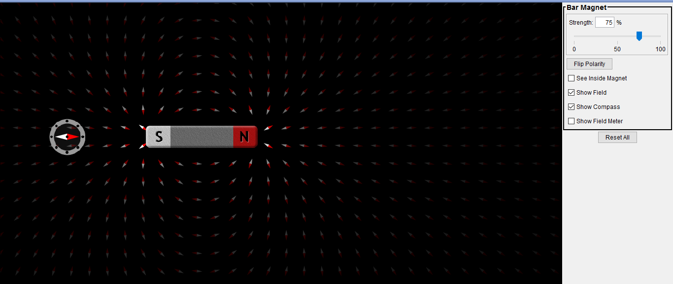
- Run the PhET simulation, “Faraday’s Electromagnetic Lab.” It should open to the Bar Magnet tab. Maximize the window. You should see a bar magnet, a compass, and a compass needle grid.
- Center the bar magnet horizontally on the fourth or fifth row from the top. Set the large compass just below the bar magnet at its midpoint. It’s okay for the two objects to be touching.
- If the compass needles (in the grid or in the large compass) are to be thought of as arrows indicating the direction of the bar magnet’s magnetic field, each one should be visualized as pointing “redward”.
- Using the on-screen slider in the control panel, run the strength of the bar magnet up and down. How does the sim show the difference between a strong magnet and a weak magnet?
- The compass needles in the grid get brighter with higher magnet strength,
and dimmer with less magnet strength. - How does the strength of the magnetic field change with increasing distance from the bar magnet and how does the simulation show this?
- The magnetic field gets weaker the further away from the magnet we get.
The simulation shows this by dimming the needles as we go. - With the magnet at its strongest, reverse its polarity using the on-screen “Flip Polarity” button in the control panel. What are the ways in which the simulation reflects this polarity reversal?
- The poles switch on the bar magnet, the big compass needle swings
around to the other side, and the grid needles all change direction. - Describe the behavior of the compass during a polarity reversal (magnet initially at 100%):
- When the compass is touching the bar magnet at its midpoint.
- The compass needle flips \( 180^{\circ} \) quite quickly. - When the compass is far from the bar magnet (touching the bottom of the simulation window), but still on a perpendicular bisector of the bar magnet.
- The compass needle flips at a considerably slower rate. - When the compass is far from the bar magnet and the magnet’s strength is set to 10%.
- The compass needle flips extremely slowly.
- When the compass is touching the bar magnet at its midpoint.
- Around the exterior of the bar magnet, the direction of the magnetic field runs from its north pole to its south pole.
- What is the direction of the magnetic field in the interior of the bar magnet? And how did you find out?
- The magnetic field points from the magnet's south pole to its north pole.
I used the built-in "See Inside Magnet" button, found on the right side of
the simulation.

Bar magnet at 100% strength.
PART B: ELECTROMAGNET
- Click the on-screen Electromagnet tab. Arrange the on-screen elements so that the top of the battery is along the second or third row of the compass grid. Notice that the magnetic field around the coil is very similar to the magnetic field around the bar magnet.
- There is no “Strength %” slider on the control panel.
- How can you change the strength of the electromagnet?
- We can change the strength of the electromagnet by changing the
voltage of the battery, using the slider on the battery itself. - In real life, is it easier to change the strength of a bar magnet or an electromagnet?
- The strength of electromagnets are far easier to adjust, as there
are no inherent methods to change the strength of a magnet.
- How can you change the strength of the electromagnet?
- There is no “Flip Polarity” button on the control panel. How can you reverse the polarity of the electromagnet?
- We can reverse the polarity of the electromagnet by changing the
direction the battery faces, which in turn changes the "direction" of
the current. - In the control panel, switch the Current Source from the battery (DC: direct current) to an oscillator (AC: alternating current). If necessary, move the electromagnet so that you can see the entire oscillator.
- What does the vertical slider on the AC source do?
- The vertical slider changes the maximum amount of current in
either direction. In terms of a trigonometric function, this is
like changing the amplitude. - What does the horizontal slider on the AC source do?
- The horizontal slider changes the time between each oscillation.
In terms of a trigonometric function, this is like changing the
period.
- What does the vertical slider on the AC source do?
- What should the sliders be set to in order to create a “dance party” display? Can you make the dance party even more annoying using the Options menu?
- To make the brightest and wackiest display possible, both the
horizontal and vertical sliders should be set 100%. If you wanted,
you could also change the background colour, using the "Options"
menu found at the top of the screen.
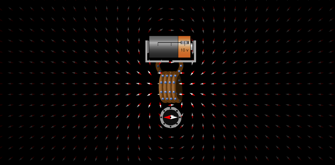
DC electromagnet. Click to enlarge!
|

AC electromagnet. Click to enlarge!
|
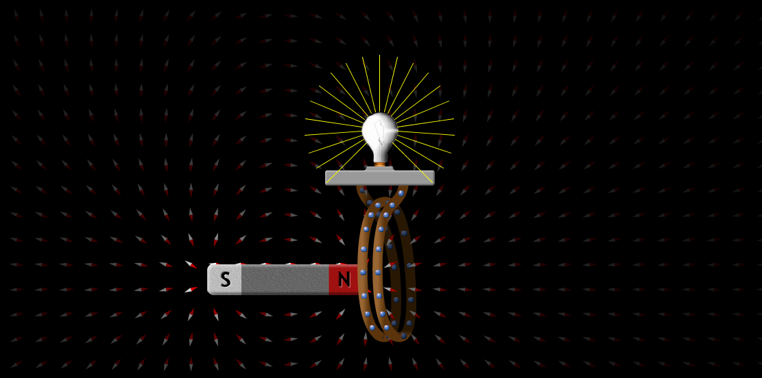
PART A: PICKUP COIL
- Run the PhET simulation, “Faraday’s Electromagnetic Lab.” Maximize the window. Click the Pickup Coil tab. You should see a bar magnet, a compass needle grid, and a coil attached to a light bulb.
- Describe the most effective way of using the magnet and the coil to light the bulb if:
- The coil cannot be moved.
- Dragging the magnet through the center of the coil repeatedly. - The magnet cannot be moved.
- Dragging the center of the coil over the magnet repeatedly.
- The coil cannot be moved.
- Rank the arrangements and motions shown below from most effective to least effective in terms of lighting the bulb, allowing for ties. For example, if A were most effective, B were least effective, and C and D were equivalent to one another, the ranking would be A > C = D > B.
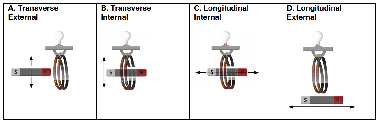
- C > B > A = D
4. Move the bar magnet through the coil and observe the motion of the electrons in the forward arc of the
coil loops. Report the correlations of magnet motion and electron motion.
coil loops. Report the correlations of magnet motion and electron motion.

a. Magnet approaches from the left, north pole first; electrons move downward.
b. Magnet departs to the right, south end last; electrons move upward.
b. Magnet departs to the right, south end last; electrons move upward.

c. Magnet approaches from the right, south pole first; electrons move downward.
d. Magnet departs to the left, north end last; electrons move upward.
d. Magnet departs to the left, north end last; electrons move upward.

e. Magnet approaches from the left, south pole first; electrons move upward.
f. Magnet departs to the right, north end last; electrons move downward.
f. Magnet departs to the right, north end last; electrons move downward.

g. Magnet approaches from the right, north pole first; electrons move upward.
h. Magnet departs to the left, south end last; electrons move downward.
h. Magnet departs to the left, south end last; electrons move downward.

Pickup coil with an unmoving magnet. Click to enlarge!
|
Pickup coil with a moving magnet. Click to enlarge!
|
PART B: TRANSFORMER
- Click the on-screen Transformer tab. You should see an electromagnet and a pickup coil.
- Experiment with the various control panel settings and the positions of the electromagnet and the pickup coil to determine a method for getting the most light out of the bulb. Describe the settings and locations.
- Electromagnet:
- Current source: AC, both bars set to 100%
- Maximum loops possible
- Placed inside or close to the loops of the pickup coil
- Pickup coil:
- Maximum loops possible
- Minimum loop area possible

Default transformer setup. Click to enlarge!
|
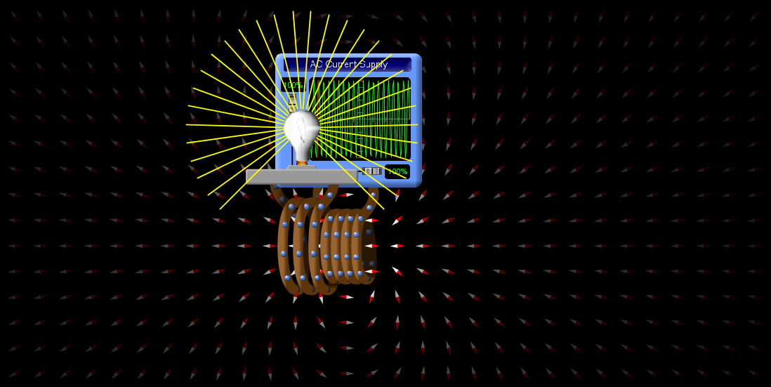
Optimal transformer setup. Click to enlarge!
|
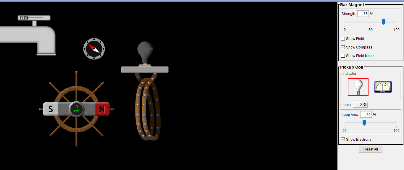
PART C: GENERATOR
- Click the on-screen Generator tab. You should see a faucet, paddlewheel with bar magnet, compass, and a pickup coil.
- Experiment with the various settings to determine a method for getting the most light out of the bulb. Describe the settings.
- Faucet:
- Maximum flow
- Magnet:
- Maximum strength
- Pickup coil:
- Maximum loops possible
- Maximum area possible - What is the story of light production here? Organize and connect the given “plot elements” and add any key elements that were omitted from the list to construct the complete story.
|
|
|
- Some of the water's kinetic energy is transferred to the paddle wheel,
causing it to spin. This rotates the magnet at the same time, leading
to a changing magnetic field. This magnetic field induces electric
current in the pickup coil, which then heats the filament in the light
bulb. This, as we're all well aware of, creates light!
causing it to spin. This rotates the magnet at the same time, leading
to a changing magnetic field. This magnetic field induces electric
current in the pickup coil, which then heats the filament in the light
bulb. This, as we're all well aware of, creates light!
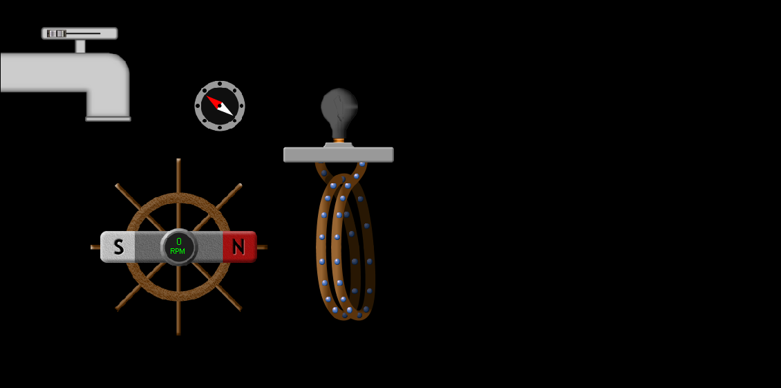
Default generator setup. Click to enlarge!
|

Optimal generator setup. Click to enlarge!
|
